Line
Create line
The line can only be added to workspace from toolbar.
Select the icon
 from toolbar to add a line.
Click on the initial point from the line in the workspace.
Click on the end point from the line in the workspace.
Note
If the toolbar is not displayed, it can be displayed from Settings > Display > Parts.
Line properties
Element part proterties can be displayed from information panel when the part is selected.
Note
If the information panel is not displayed, it can be displayed from Settings > Display > Information.
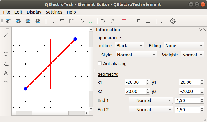
Figure: QElectroTech line from element
QElectroTech allows customizing different line properties:
- Appearance:
- Color:
The outline and filling color of the part can be defined from a list of pre-defined colors. At the case of the line part the filling color is None.
- Style:
The outline representation type can be chosen between: Normal (Continuous), Dashed, Dotted or, Dots and dashes.
- Thickness:
The outline thickness (Weight) can be chosen between: None, Thin, Normal, Strong or High.
- Geometry:
- Coordinates:
The start and end point coordinates (x, y) can be defined.
- End point:
The extreme point from the line can be represented individually as:
- Normal:
The extreme point is represented as the rest of the line, there is no different representation for the end point.
- Simple arrow:
The extreme point is represented as a filled arrow.
- Triangle arrow:
The extreme point is represented as an empty triangle arrow.
- Circle:
The extreme point is represented as an empty circle.
- Diamond:
The extreme point is represented as an empty diamond.